
-

Schicken Sie uns eine E-Mail
sale@lscmagnetics.com -

Kontaktnummer
+86 -13559234186
Schicken Sie uns eine E-Mail
sale@lscmagnetics.comKontaktnummer
+86 -13559234186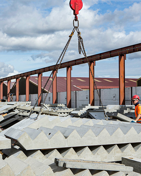

What Factors Affect the Load Capacity of a Precast Concrete Lifting Socket?
Nov 20, 2026Lifting Sockets are critical to precast components from demolding through final placement on site. They may look like minor details on the drawings, but in practice they determine whether a wall panel or composite beam—weighing anywhere from a few tons to more than a dozen—can be safely rotated, lifted, and set in place. Insert failures are not uncommon, and they tend to follow a few consistent failure modes: anchor pull-out, local concrete crushing around the anchor plate, splitting cracks along the anchors, and punching shear around the lifting point. Preventing these problems starts with recognizing that the capacity of a lifting socket is not a fixed number taken from a calculation; it is the combined effect of material properties, structural detailing, load path, and construction quality.
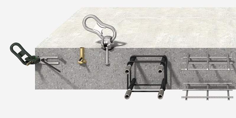
These are the "intrinsic" factors that govern capacity—and they are often overlooked.
Anchor bars: Bar diameter, number, anchorage length, spacing, and layout govern tensile, shear, and pull-out resistance. If anchorage length is insufficient, the failure mode shifts from steel yielding to concrete cone pull-out—a transition that causes a sharp drop in capacity and results in brittle failure. Hooks or end plates can significantly improve anchorage.
Anchor plates: Thin plates can bend or yield near the welds, while undersized plates increase the risk of local concrete crushing and punching shear. How uniformly force transfers from the plate into the concrete depends on contact-surface flatness and how well welding distortion is controlled.
Weld quality and connections: Undersized weld legs, porosity, slag inclusions, incomplete fusion, or failure to remove slag and apply anti-corrosion coating after welding can all become initiation points for fatigue and corrosion. Welds at lifting points that see dynamic loads need particularly rigorous inspection.
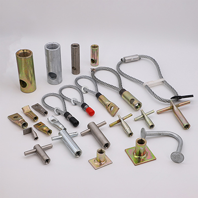
Insert type: Load transfer differs by insert type—cast-in lifting studs, recessed lifting loops, or welded anchor-plate assemblies. Stud anchors are more sensitive to local concrete bearing stress and splitting, while welded anchor-plate assemblies depend more on bar anchorage and weld quality.
Practical tip: Do not treat "the total anchor-bar area checks out in the calculation" as the sole acceptance criterion. Anchorage length, edge distance, spacing, and weld quality are all part of capacity—none can be ignored.
Inserts do not work in isolation; much of their performance depends on the surrounding concrete.
Strength grade and age: Higher concrete strength improves bond anchorage, local bearing, and punching-shear resistance. More importantly, what matters is the actual strength at the time of lifting, not the design strength. Industry practice generally requires lifting strength to be at least 75% of the characteristic design strength (check current standards and the project-specific plan for exact requirements). Risks rise in winter construction, early formwork removal, and when schedules are compressed.
Vibration and compaction: Inadequate vibration—or over-vibration that causes segregation—around inserts can produce honeycombing or voids and reduce the effective bond length of the anchors. Poor air release beneath large anchor plates can also create voids.
Curing and cracking: Insufficient curing leads to low early-age strength and more shrinkage cracking. If cracks intersect the lifting-point zone, local capacity drops significantly.
Aggregate size and grading: Oversized aggregate or poor grading can cause aggregate bridging—voids forming between coarse particles—in areas with congested anchor reinforcement, reducing effective bond.
Practical tip: Confirm that field-cured specimens meet the lifting-strength requirement before authorizing the lift—do not rely solely on standard-cured specimens. The casting and vibration around lifting points should be a focus of pre-pour (concealed-work) inspections.
Many failures occur not because the inserts themselves are too weak, but because they are subjected to forces the original design did not account for.
Lifting points relative to the center of gravity: If lifting points are offset from the center of gravity, additional bending and torsion are introduced. Load redistributes among the points, potentially overloading the most critical one to several times its design load.
Sling angles: Shallower angles (measured from the horizontal) produce larger horizontal force components. This creates combined tension–shear loading—or even a tearing action—on the inserts and increases the risk of splitting along the component edges. Standards and lifting plans typically limit the angle between slings and the horizontal; shallower angles are generally more adverse.
Dynamic loads and start-up impact: Acceleration, braking, wind, and vibration during lifting amplify the applied forces—a factor normally handled in design through a dynamic coefficient. Abrupt starting or stopping on site can significantly magnify these effects.
Uneven load sharing among multiple lifting points: Differences in wire-rope length, structural deformation, or lifting-point elevation can cause some points to pick up load earlier or carry a disproportionate share of the weight.
Turning, tailing, and in-air orientation: During panel turning (rotation), the direction and magnitude of the forces on the lifting points change continuously. This places demands on both the inserts and the component itself.
Eccentric lifting and one-sided loading: During the initial lift (demolding), formwork suction/adhesion can significantly increase the instantaneous load. Accidental eccentricity can also arise if the lifting gear catches on truss reinforcement (in composite slabs) or exposed bars.
Practical note: A lifting plan should specify not just the weight to be lifted but exactly how the lift is to be executed—lifting-point layout, sling angles, turning angles, tailing procedure, and wind-speed limits. A check based only on weight, without a full analysis of the actual operating conditions, is incomplete.
Capacity depends heavily on how the surrounding concrete performs.
Edge distance and member thickness: If a lifting point sits too close to a slab edge, a wall end, or within a thin member, concrete cone failure or splitting may occur prematurely, which reduces the effective anchorage depth. Thin-walled members are particularly vulnerable.
Anchor spacing and row spacing: Insufficient spacing causes a group effect, in which the concrete cones of individual anchors overlap and total capacity is less than the sum of the individual capacities. Excessive spacing, conversely, increases bending moment on the anchor plate.
Concrete cover: Inadequate cover can lead to surface splitting and reinforcement corrosion, while excessive cover can reduce the effective anchorage zone. Lifting zones often have congested reinforcement, making the required cover difficult to achieve.
Local bearing and punching shear: Stress concentrates beneath the anchor plate; if member thickness or reinforcement is insufficient, punching shear failure can occur. This failure is sudden and gives little warning, so it must be checked separately in lifting-point design.
Proximity to other inserts or openings: Mechanical/electrical openings, conduit boxes, or other inserts near a lifting point can disrupt the load path and create a plane of weakness.
Practical tip: During detailed design, run a clash check to ensure inserts do not conflict with reinforcement or openings. In lifting zones, consider adding anti-cracking reinforcement—such as a steel mesh or spiral—to control splitting cracks.
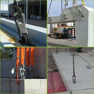
Even the best design can be compromised by poor execution on site.
Positioning deviations: A tilted insert, wrong elevation, or horizontal displacement can change the actual direction of the applied force, turning a simple axial-tension case into eccentric tension plus shear. Specify permissible tolerances in the work instructions and verify actual positions by on-site measurement.
Movement during casting: Inserts commonly shift—floating up, sinking, or rotating—during vibration. Use reliable fixing frames and check positioning again after pouring.
Surface contamination and interface preparation: Dust or form-release agent on anchor-plate surfaces can interfere with subsequent welding or structural connections. Inadequate roughening or cleaning of interfaces—such as those for secondary pours or closure strips—can result in poor bond.
Formwork removal and lifting timing: Forcing a lift while the component is still strongly adhered to side or bottom formwork can impose instantaneous loads far exceeding the component's own weight, often damaging inserts and the edges or corners of the component.
Reuse: Reusable lifting hardware must be inspected for fatigue damage and thread wear. Do not weld temporary reinforcement directly onto main reinforcement or inserts.
Practical tip: Implement QR-code traceability for inserts. By linking specifications, batch/heat numbers, installation locations, and inspection records, any issue can be traced quickly to the crew and concrete batch.
Corrosion: Corrosion of anchor bars and plates reduces cross-sectional area. Rust expansion can also crack the concrete cover, creating a vicious cycle: reduced capacity → crack widening → accelerated corrosion. In humid, marine, or de-icing-salt environments, the level of corrosion protection must be upgraded.
Freeze–thaw and high temperature: Freeze–thaw cycles can damage surface concrete and weaken the anchorage zone. Exposure to fire or high-temperature operations (such as welding heat) can degrade the mechanical properties of both steel and concrete.
Chemical attack: Some curing agents, form-release agents, or concrete admixtures may chemically attack the steel or the bond interface; verify compatibility.
Practical tip: Seal or coat exposed inserts. For lifting points that need inspection or maintenance over the design service life, the drawings must clearly show that they are accessible and inspectable.
On-site re-verification: Check material certificates and the mechanical properties of anchor bars and plates; visually inspect welds and supplement with non-destructive testing (NDT) where necessary.
Concealed-work inspection: Before concrete placement, verify insert positioning, securement, spacing, cover, and reinforcement layout.
In-situ pull-out/spot testing: Perform pull-out tests on critical lifting points or on batches of questionable quality; this is the most direct way to verify anchorage integrity.
Joint pre-lift inspection: Confirm that all requirements are met—strength test reports, lifting gear and rigging, condition of lifting points, weather conditions, and a designated signal person.
Quick On-Site Self-Check Checklist (printable for pre-lift briefings):
Concrete has reached the required strength (verified with field-cured specimens) and the test report is still valid.
Lifting-point locations and labels match the approved plan, with no obstructions or collision risk.
Inserts are free from rust, deformation, or concrete damage/cracking.
Sling angles, reeving, and shackle orientation match the engineering calculations.
A trial lift has been performed (hoist 200–300 mm off the ground and hold) to check load distribution at each lifting point and component orientation.
Wind speed, lighting, and exclusion zones meet the plan's requirements; a single designated signal person is assigned.
If any abnormal noise, swaying, or cracking occurs, lower the load immediately—never force the lift.
Whatsapp : +86 -13559234186
E-Mail : sale@lscmagnetics.com
Tel : +86 -13559234186