-

Schicken Sie uns eine E-Mail
sale@lscmagnetics.com -

Kontaktnummer
+86 -13559234186
Schicken Sie uns eine E-Mail
sale@lscmagnetics.comKontaktnummer
+86 -13559234186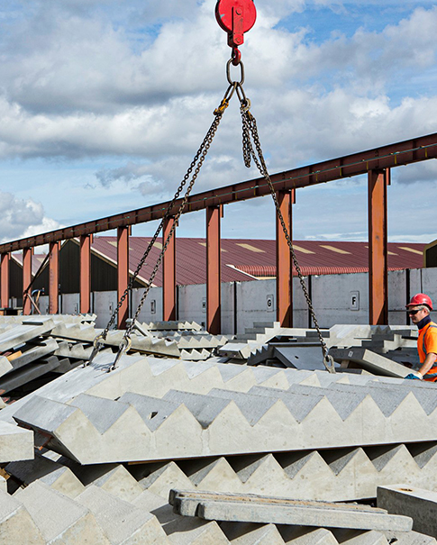

Lifting sockets (also known as internally threaded lifting sleeves or cast-in lifting sleeves) connect to the rigging via an internal thread. They are the most commonly used lifting points for thin-walled components such as precast wall panels, composite slabs, and stairs. Unlike solid ball anchors, the load-bearing capacity of a socket is often governed by the concrete rather than the steel—the same socket that safely lifts 5 tonnes on one site may be dangerous at even 2 tonnes on another.
Before analysing the influencing factors, you need to know how a socket fails:
Steel failure: thread stripping or rupture of the sleeve body—the highest-capacity mode, and rarely governing.
Pull-out failure: the entire sleeve is pulled out of the concrete—occurs when embedment depth is insufficient and concrete strength is low.
Concrete cone failure (cone splitting): the concrete in front of the socket breaks away in a frustum shape—the most common governing mode, and heavily influenced by edge distance, slab thickness, and reinforcement.
The design capacity of a socket is the minimum of the three modes above. Every factor discussed below essentially shifts the balance between them.
Socket capacity is roughly proportional to the tensile strength of the concrete, which in turn increases with cube/cylinder strength. In practice, three concepts must be distinguished:
| Strength concept | Misunderstanding | Correct practice |
| Design strength C30/C40 | This is the 28-day standard-cured value, not the strength at lifting | For long-term reference only |
| Release strength | Determines the anchorage capacity of the socket | Use companion test blocks or rebound testing on site |
| Local strength around the socket | Reduced by early age, low temperature, and uneven curing | Extend the demolding waiting time in cold weather |
Practical tip: In winter production, strength can vary by more than 30% across different parts of the same slab. Sockets should be located in areas with adequate placing and vibration, and the best curing conditions.
Embedment depth determines the volume of both pull-out and cone failure. Thin slabs are often forced to use short sockets, in which case:
Capacity decreases roughly linearly with embedment depth;
The manufacturer should be asked to provide a capacity table corresponding to embedment depth, not just a nominal value;
Cutting or welding the load-bearing sleeve "to shorten it" on site is prohibited.
Slab thickness directly limits the development of the sliding surface for cone failure. When slab thickness is less than the manufacturer's minimum:
The mode may change to punching failure, with a sudden drop in capacity;
A socket with a load-spreading plate or adapter plate is required;
For sandwich/laminated panels, account must be taken of whether the wythe thickness participates in load transfer.
The horizontal distance from the socket axis to the slab edge (edge distance) and the clear distance between adjacent sockets (spacing) determine whether the concrete cone can form fully:
Insufficient edge distance: part of the cone is "cut off" at the side, significantly reducing the failure load, often accompanied by edge spalling;
Insufficient spacing: adjacent cones overlap, producing a group anchor effect in which no single socket reaches its nominal capacity;
At the selection stage, the minimum edge distance/spacing must be checked against the manufacturer's charts. Irregular and perforated slabs require separate checks.
Mesh or additional reinforcement around the sockets can:
Restrain crack development and delay cone splitting;
Spread tensile forces over a larger volume of concrete;
Change the failure mode from brittle splitting to ductile steel yielding.
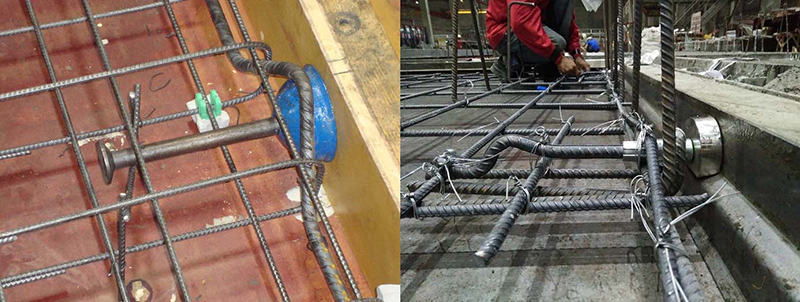
Installing additional mesh (commonly Ø6–Ø10, double-layer, at 50–100 mm spacing) above the socket, as shown in the manufacturer's drawings, is the most cost-effective way to "amplify" capacity.
The nominal capacity of a socket is usually quoted for a pull perpendicular to the slab surface (axial). Under real conditions:
| Load condition | Change in capacity | Countermeasure |
| Axial pull | Nominal value | — |
| Shear parallel to slab | May drop to 30%–50% | Use dedicated shear sockets or additional shear keys |
| Oblique pull (e.g., tilting) | Reduced according to angle; tension and shear combined | Stay within the manufacturer's permitted angle; select a tilt-capable model |
| Eccentric load (sling deflection) | Additional bending moment accelerates splitting | Control sling deflection; avoid diagonal or shock loading |
Formwork adhesion at the moment of demolding, plus braking and travel impacts, can push the actual load well above the static value:
The dynamic coefficient for demolding is generally 1.3–1.5, with the higher value for sticky formwork or large panels;
The socket WLL should be ≥ static load × dynamic coefficient ÷ number of lifting points, with a margin of more than 20%;
Inertia forces must also be considered for tilting and mid-air rotation, with the load reduced where necessary.
The causes of frequent on-site rework often lie not in the product itself:
Verticality deviation: a tilted socket axis turns the load into eccentric pull and reduces the thread engagement length;
Grout leakage and blocked holes: if the core hole is not capped or the cap fails, the thread cannot be fully engaged and the effective number of turns is reduced;
Vibration segregation: laitance collects at the base of the socket, aggregate sinks, and local strength falls below the slab average;
Cover deviation: a socket buried too shallow directly weakens anchorage.
Socket positioning should be included in formwork acceptance checks, and thread engagement should be checked by hand on every socket after demolding.
Coastal and de-icing salt environments: corroded carbon-steel sockets lose section, threads seize, and both capacity and ease of removal are reduced—specify galvanized or stainless steel;
Repeated lifting: record the cumulative number of lifts for each socket, and scrap it once the manufacturer's specified cycle count is reached (typically tens to hundreds of lifts, depending on tonnage). Fatigue cracks often initiate at the thread root.
Finally, the product parameters themselves:
Material and process: machined steel parts outperform cast parts, and thread accuracy affects stress concentration;
WLL-to-breaking-load ratio (safety factor): 3:1 to 5:1 is common in the industry; the lower the value, the greater the risk of non-compliant products;
Certification scope: whether the slab thickness, edge distance, and concrete strength grade covered by the third-party report match your site conditions—using the product outside its certified boundary may invalidate insurance cover.
Q: How much should the capacity of a socket at a slab corner be reduced?
It depends on the edge distances. Where corner edge distances are limited in both directions, the cone volume is greatly reduced and capacity may reach only 40%–60% of the nominal value. It must be reduced in accordance with the manufacturer's corner-coefficient table, or special corner anchors or additional lifting points should be used.
Q: What is the effect of a 2 MPa difference in concrete strength?
The relationship between tensile and compressive strength is approximately a power function. At the low-strength end (e.g., 12 → 10 MPa), a 2 MPa difference can cost more than 15% of tensile strength—enough to change the failure mode. "It'll probably hold" is not an acceptable approach.
Q: How should the holes left after removing the socket be treated?
Seal them as specified in the design: load-bearing components should be sealed with grout or anchor adhesive plus corrosion protection; decorative surfaces can be repaired with colour-matched mortar. Before sealing, clean debris from the holes and pre-wet them to avoid creating new seepage paths.
Q: Can expansion bolts be used as lifting points instead of lifting sockets?
Absolutely not. Expansion bolts are designed to secure static loads; their tensile mechanism (friction plus wedging) can fail instantaneously, with unpredictable failure modes, under vibration and impact.
Whatsapp : +86 -13559234186
E-Mail : sale@lscmagnetics.com
Tel : +86 -13559234186